 HYDRX: FUEL CONDITIONING SYSTEM
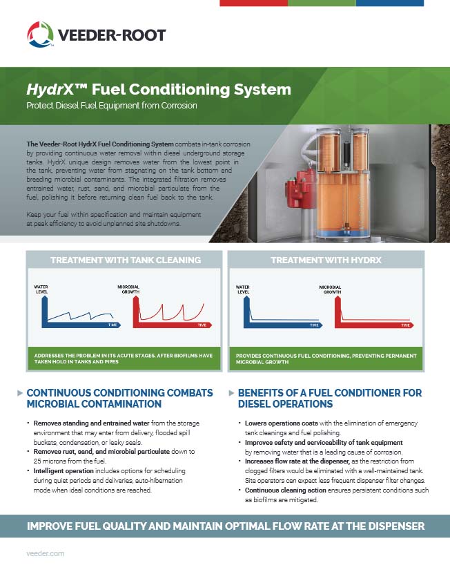
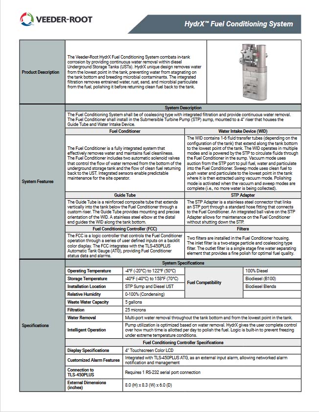
The Veeder-Root HydrX Fuel Conditioning System combats in-tank corrosion by providing continuous water removal within diesel Underground Storage Tanks (USTs). The unique design of the HydrX Fuel Conditioning System removes water from the lowest point in the tank, preventing water from stagnating on the tank bottom and breeding microbial contaminants. The integrated filtration removes entrained water, rust, sand, and microbial particulate from the fuel, polishing it before returning clean fuel back to the tank.
The primary components of the HydrX Fuel Conditioning System are:
• Fuel Conditioner
• Water Intake Device & Guide Tube
• Fuel Conditioning Controller
 Fuel Conditioner
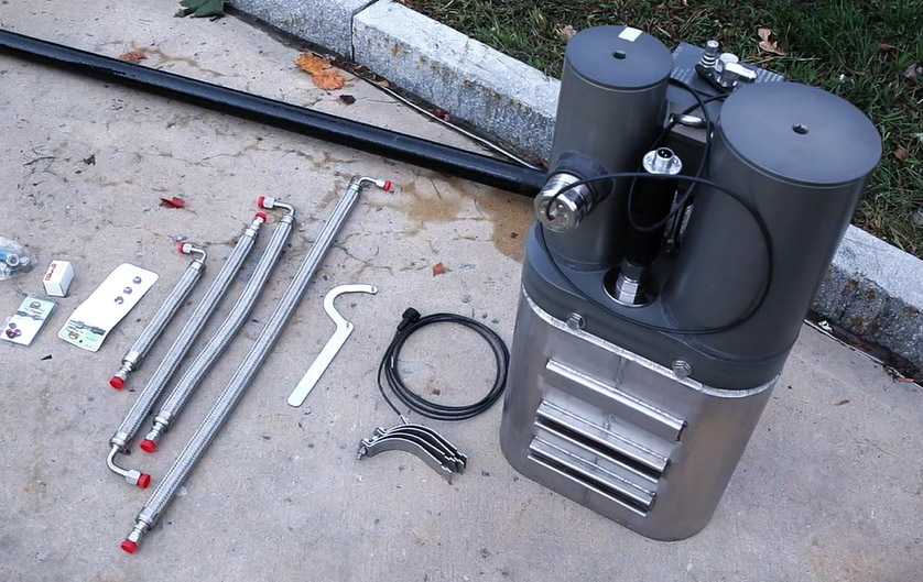
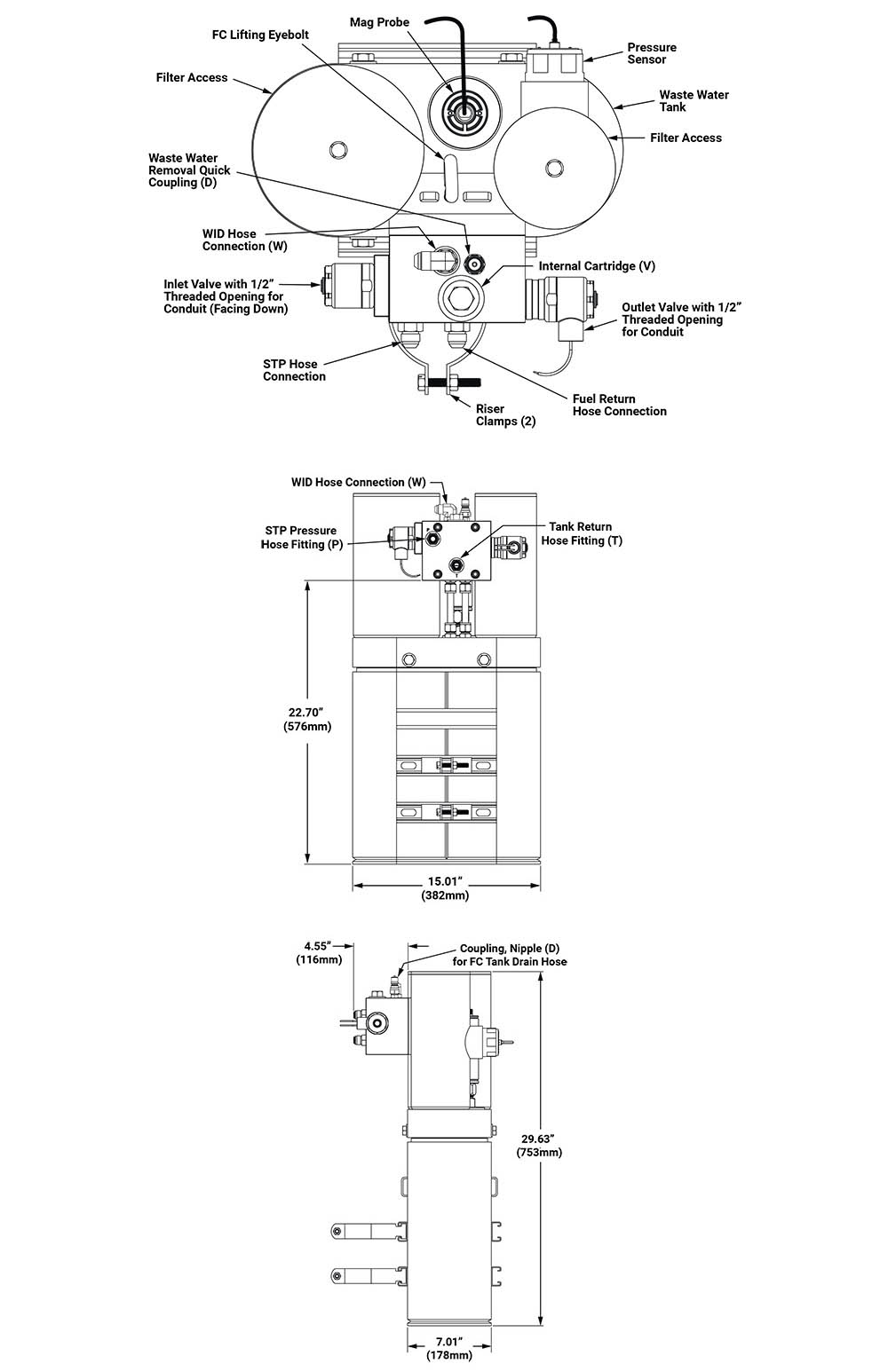
The Fuel Conditioner is a fully integrated system that effectively removes water and maintains fuel cleanliness. The Fuel Conditioner includes two automatic solenoid valves that control the flow of water removed from the bottom of the underground storage tank and the flow of clean fuel returning back to the UST. Integrated sensors enable predictable maintenance for the site operator.
There are two filters installed in the Fuel Conditioner housing. The inlet filter is a two-stage particle and coalescing type filter. The outlet filter is a single stage fine water separating element that provides a fine polish for optimal fuel quality.
 Fuel Conditioner Components

| Part Number | Description |
| 860580-050 | Fuel Conditioner (5 gallon water holding capacity) |
| 330020-867 | Kit - Fuel Conditioning System (FCS) Riser - 15.5" Length |
| 330020-885 | Kit - Valve Conduit |
| 330020-868 | Kit - Fuel Conditioner Filter Cartridges |
| Part Number | Description | Options: A or B, C or D |
| 330020-875 | Kit – TRJ Installation (Option A) | Option A or Option B |
| 330020-874 | Kit – FE Installation (Option B) | |
| 330020-880 | Kit – Water Drain (Option C) | Option C or Option D |
| 330020-884 | Kit – Water Drain Quick Coupling (Option D) |
 Water Intake Device (WID)
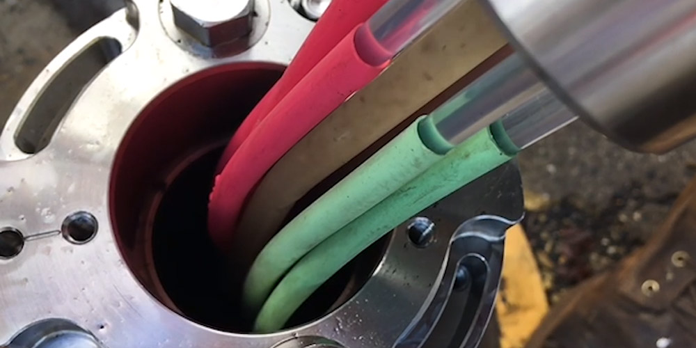
The WID contains 1-6 fluid transfer tubes (depending on the configuration of the tank) that extend along the tank bottom to the lowest point of the tank. The WID operates in multiple modes and is powered by the Submersible Turbine Pump (STP) to circulate fluids through the Fuel Conditioner in the sump.
• Vacuum mode uses suction from the STP port to pull fuel, water and particulate into the Fuel Conditioner.
• Sweep mode uses clean fuel to push water and particulate to the lowest point in the tank where it is then extracted using vacuum mode.
• Polishing mode is activated when the vacuum and sweep modes are complete (i.e., no more water is being collected).
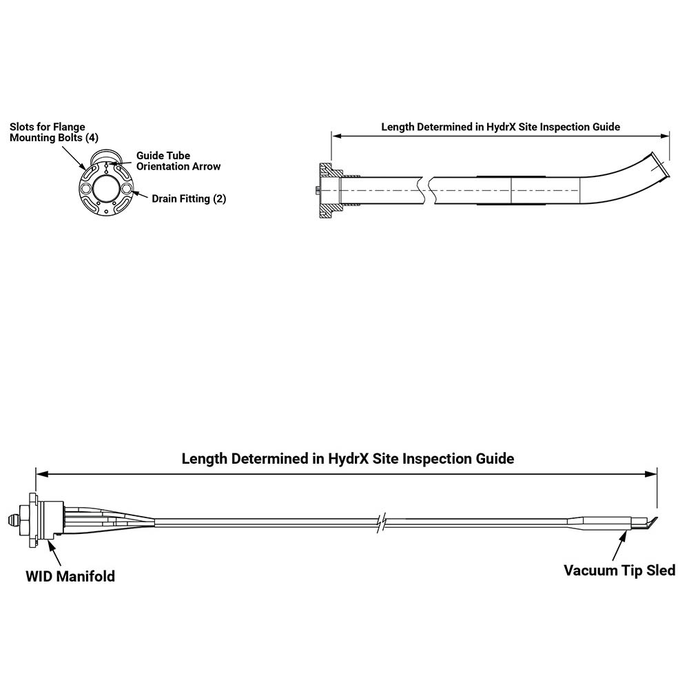
Water Intake Device Guide Tube
The Guide Tube is a reinforced composite tube that extends vertically into the tank below the Fuel Conditioner through a custom riser. The Guide Tube provides mounting and precise orientation of the WID. A stainless steel elbow at the distal end guides the WID along the tank bottom.Water Intake Device Components
| Part Number | Description | Overall Length |
| 860801-XXX | Water Intake Device (WID) for Fiberglass Tank with 1 Tube | Last three digits run 143 to 600 (increments in 1 inch)
Example: 860816-500 500” WID for 8’ diameter fiberglass tank with 6 tubes |
| 860813-XXX | WID for 8' Diameter Fiberglass Tank with 3 Tubes | |
| 860816-XXX | WID for 8' Diameter Fiberglass Tank with 6 Tubes | |
| 860823-XXX | WID for 10' Diameter Fiberglass Tank with 3 Tubes | |
| 860826-XXX | WID for 10' Diameter Fiberglass Tank with 6 Tubes | |
| 860780-XXX | Guide Tube | 107, 113, or 135 (inches) |
 Fuel Conditioning Controller
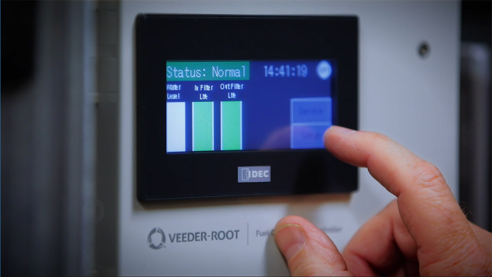
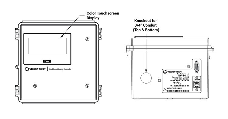
The Fuel Conditioning Controller is a logic controller that controls the Fuel Conditioner operation through a series of user defined inputs on a backlit color display. The Fuel Conditioning Controller integrates with the TLS-450PLUS ATG, providing Fuel Conditioner status data and alarms.
Fuel Conditioning Controller Part Number
| Part Number | Description |
| 860400-001 | Fuel Conditioning Controller - 6' Cable |
Fuel Conditioning Controller Specifications
| Display Specifications | 4" Touchscreen Color LCD |
| Customized Alarm Features | Integrated with TLS-450PLUS ATG, as an external input alarm, allowing networked alarm notification and management |
| Connection to TLS-450PLUS | Requires 1 RS-232 serial port connection |
| External Dimensions (inches) | 8.0 (H) x 8.3 (W) x 6.0 (D) |
HydrX System Specifications
| Component Approvals | Solenoid Valve: UL/cUL recognized components, reference UL/cUL E37780
Intrinsically Safe Sensors: UL/cUL listed, reference UL/cUL MH11766 Fuel Conditioning Controller: UL/cUL listed, reference UL/cUL E102542 |
| Fuel Conditioner External Dimensions (inches) | 30 (H) x 15 (W) x 12 (D) |
| Operating Temperature | -4°F (-20°C) to 122°F (50°C) |
| Storage Temperature | -40°F (-40°C) to 158°F (70°C) |
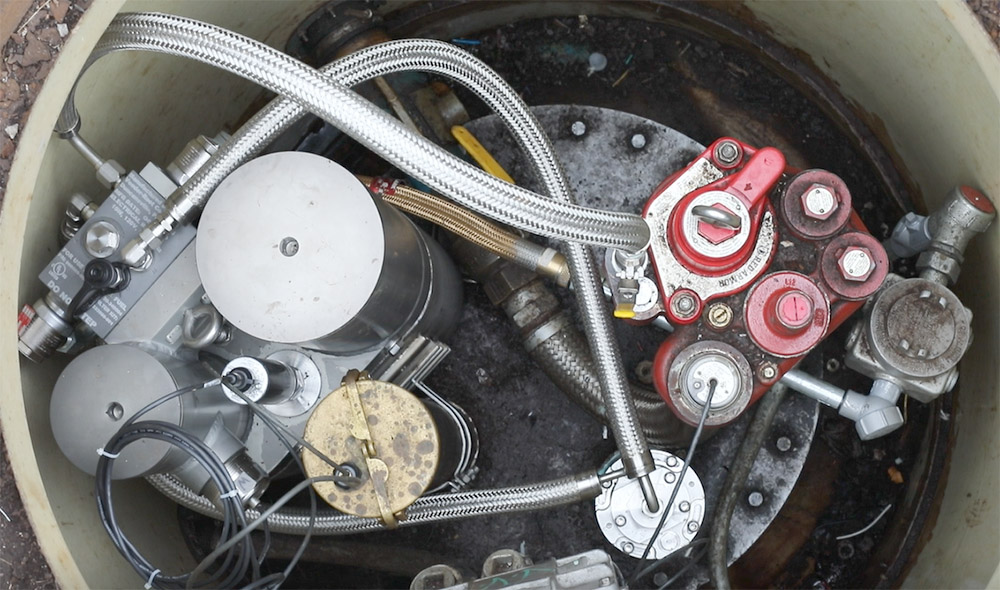
| Installation Location | STP Sump and Diesel UST |
| Relative Humidity | 0-100% (Condensing) |
| HydrX Solenoid Valve Power Requirements (to the sump) | AC Power Wiring carrying 120 VAC control circuit to power solenoid valves on a separate breaker. Local electrical codes or site requirements may also require a separate Emergency Stop Control. Minimum wire size shall be 14 AWG. 4 wires total: 2 wires for valve control voltage, 1 common neutral and 1 earth ground. |
| HydrX Sensor Wiring Requirements | 1. Wire Type – Shielded cable required regardless of conduit material or application. Shielded cable must be rated less than 100 picofarad per foot manufactured with a suitable material such as Carol C2534 or Belden 88760, 8760, or 8770.
2. Wire Length – Maximum 1,000 ft to meet intrinsic safety requirements. Improper system operation could result for runs over 1,000 ft. 3. Wire Gauges – Color coded – shielded cable used in all installations. Wires should be #14 - #18 AWG stranded copper wire and installed as Class 2 circuits. As an alternate method when approved by the local authority having jurisdiction, #22 AWG wire such as Belden 88761 may be suitable with the following requirements: Wire run is less than 750 ft; Capacitance does not exceed 100 pF/ft; Inductance does not exceed 0.2 uH/ft. |
| Fuel Conditioning Controller Power Requirements | AC Power Wiring carrying 120 VAC from the power panel to the controller should be #14 AWG (or larger) copper wire for line, neutral and chassis ground (3). |
| Waste Water Capacity | 5 gallons |
| Filtration | 25 microns |
| Water Removal | Multi-port water removal throughout the tank bottom and from the lowest point in the tank. |
| Intelligent Operation | Pump utilization is optimized based on water removal. HydrX gives the user complete control over how much time is allotted per day to polish the fuel. Logic is built-in to prevent freezing under extreme temperature conditions. |
System Construction
| Fuel Conditioner | |
| Lifting Eyebolt | Stainless Steel |
| Waste Water Tank | Stainless Steel |
| Water Removal Fitting | Stainless Steel |
| WID Hose Connection | Stainless Steel |
| Filter Housing & Access Caps | Anodized Aluminum |
| Solenoid Manifold | Anodized Aluminum |
| Guide Tube | |
| Elbow | Stainless Steel |
| Guide Tube Flange | Stainless Steel |
| Tube | Fiberglass Reinforced Composite |
| Water Intake Device (WID) | |
| Body | Stainless Steel |
| Fittings | Stainless Steel |
| Vacuum Tip Sled | Stainless Steel |
| WID Manifold | Stainless Steel |
| Intake Lines | Fluorinated Ethylene Propylene (FEP) |
| Sleeve | Polyethylene / Polyester |